- High-concerned chemical: None
- Application: Milling Machine
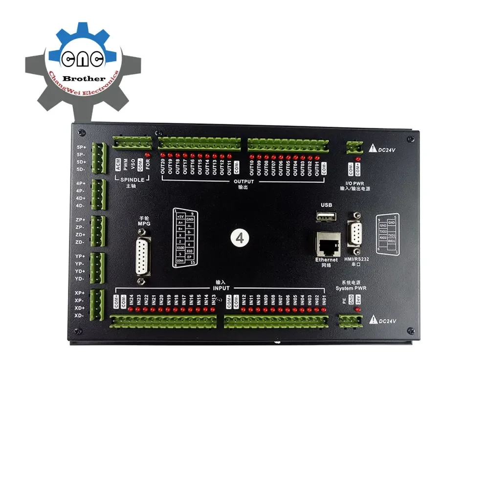
- Model Number: M350 Kit
- Origin: Mainland China
- Certification: None
- Origin: Mainland China
- Certification: none
- Application: Milling Machine
- Model Number: M350 Kit
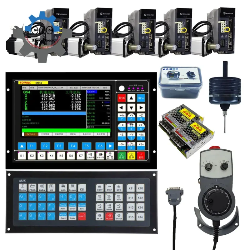
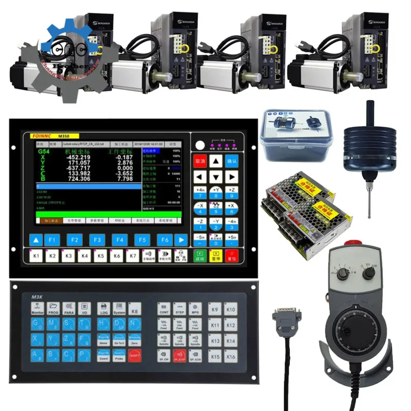
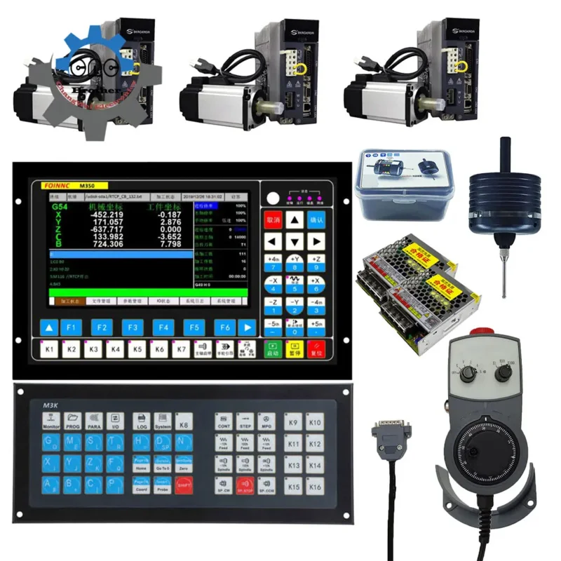
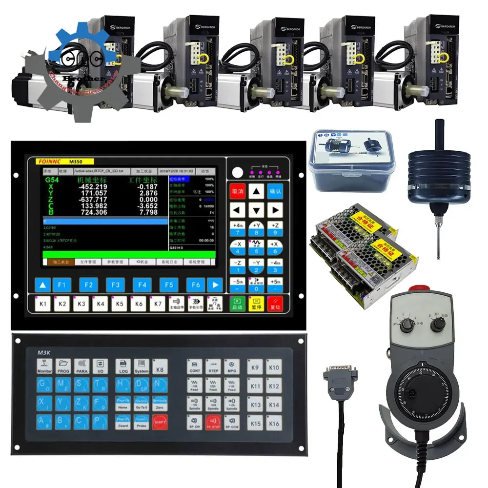
Product content:
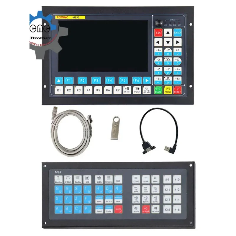
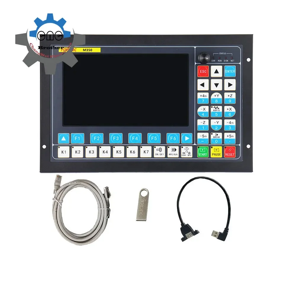
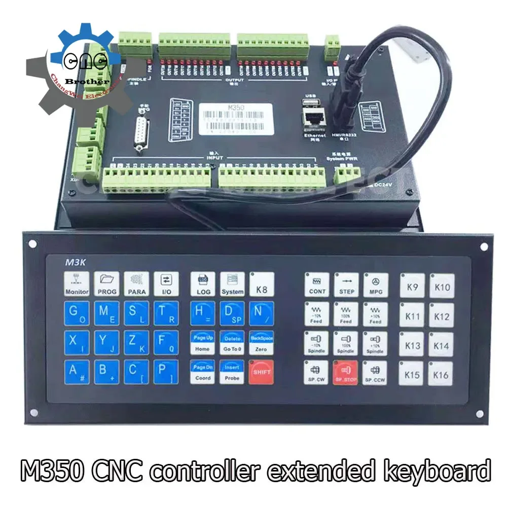
1xM350 CNC controller (3, 4, 5 axes optional)
1x3d edge finder (with cable)
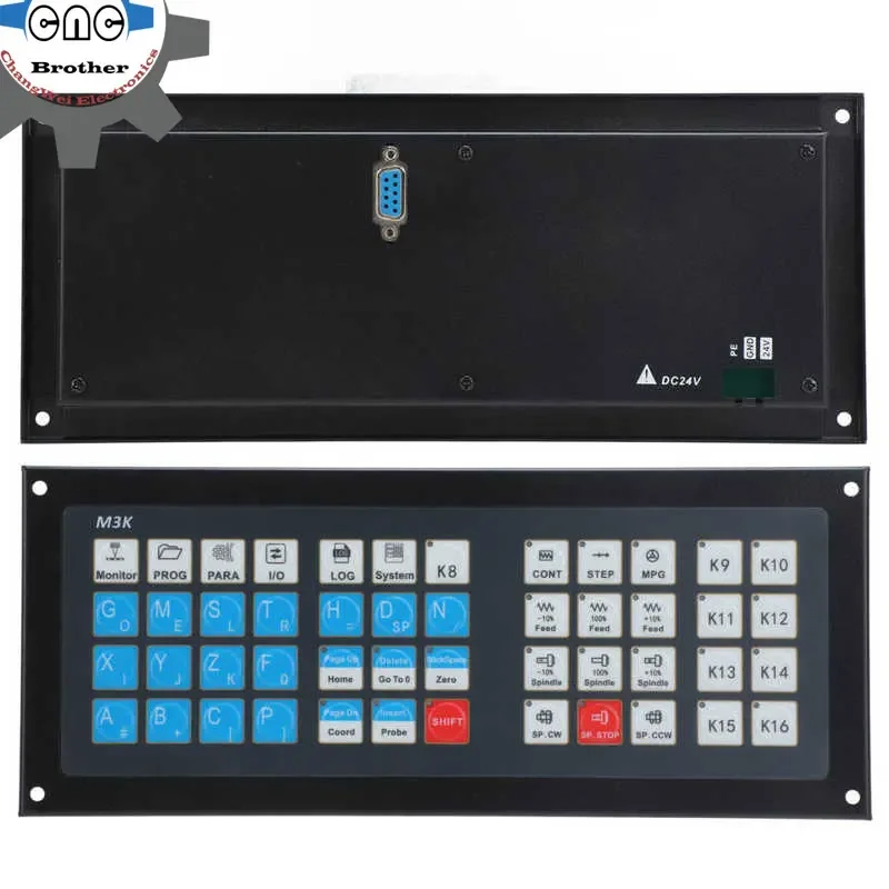
1xM3K expansion keyboard (with cable)
1xUSB extension cable
1xUSB
1x network cable
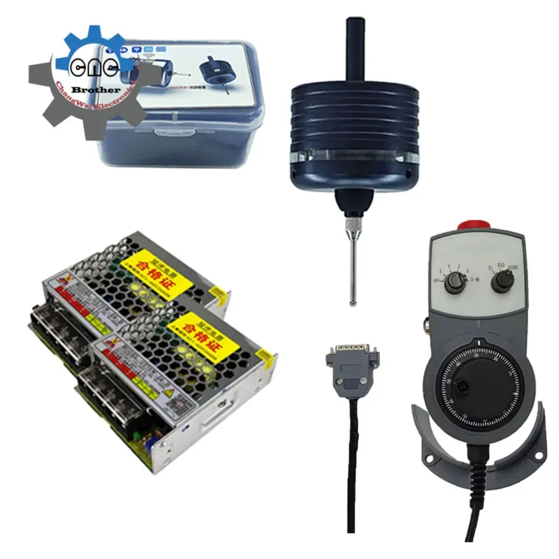
1x electronic handwheel mpg
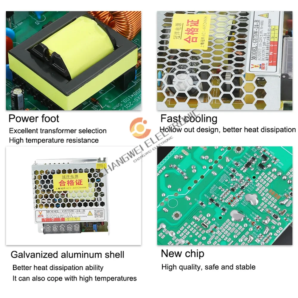
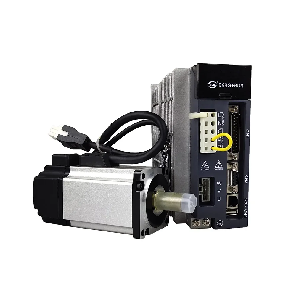
2x75W24VDC
Note:
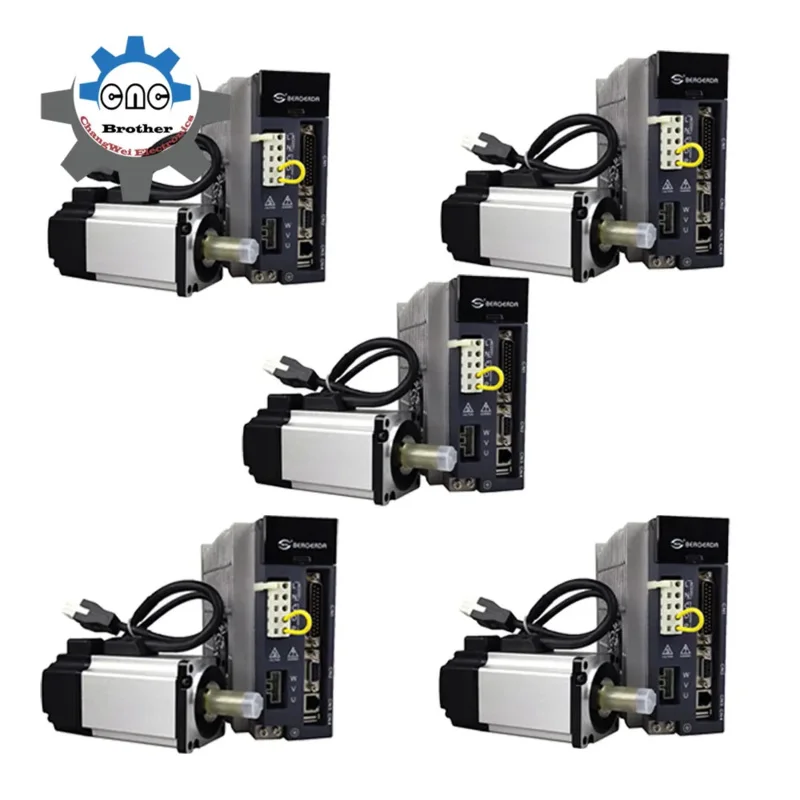
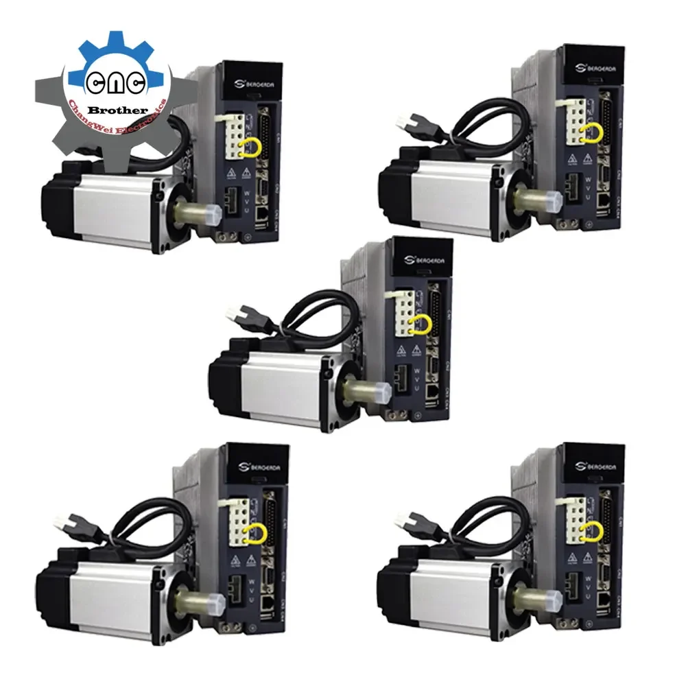
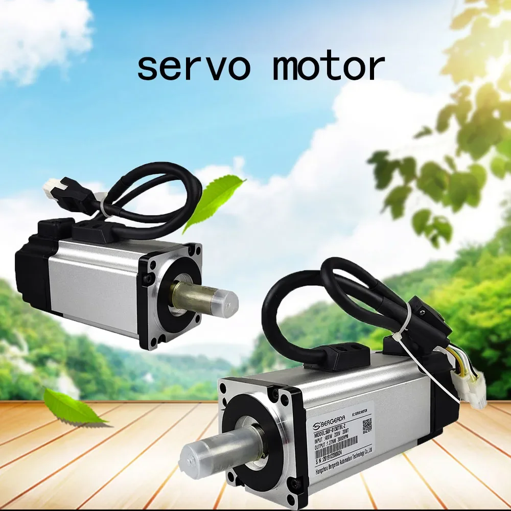
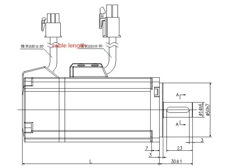
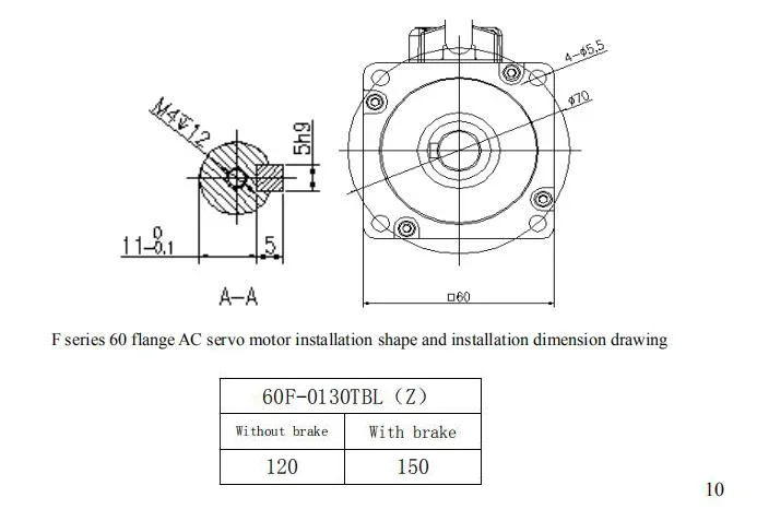
The 3-axis kit is equipped with three sets of 750w 220v servo motors and drives, including one set of Z-axis with brakes.
The 4-axis kit is provided with four sets of 750w 220v servo and drive, one of which is Z-axis with brake.
The 5-axis kit is equipped with five sets of 750w 220v servo motors and drives, including one set of Z-axis with brakes.
Introduction:
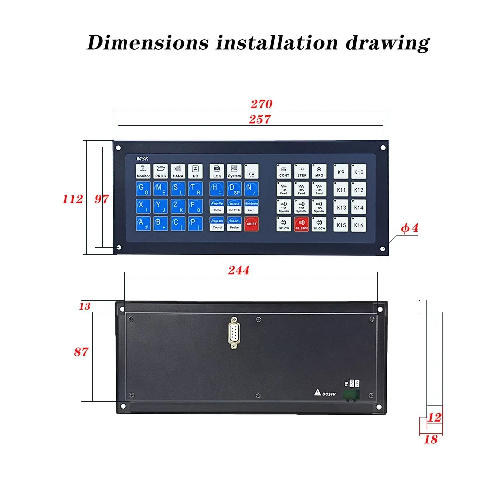
The system M350 is a professional 3-5 axis motion controller based on an embedded platform. It is equipped with a 7-inch full-color screen, full keyboard input, and customizable function keys to make user operation more convenient. It supports multi-process, straight-line tool magazine, circular Disk tool magazine function. The interface and structure adopt the mainstream method in the market, with simple operation, easy to learn and understand, and convenient installation. The system uses advanced adaptive speed forward control algorithm, which has the characteristics of high processing efficiency and good surface quality. Meet the needs of various engraving machines, engraving and milling machines, cutting machines.
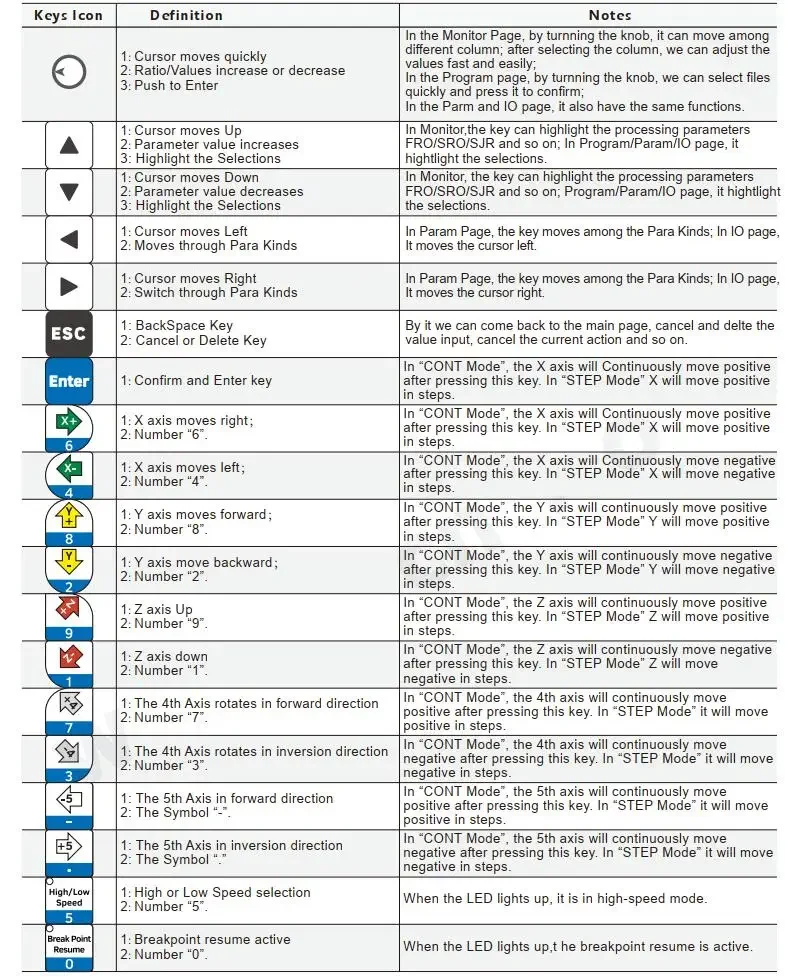
System Features:
Maximum number of control axes: M350 five-axis, 2-5 axis linear interpolation, arbitrary 2-axis circular interpolation;
Operation mode: Mainstream engraving machine system operation;
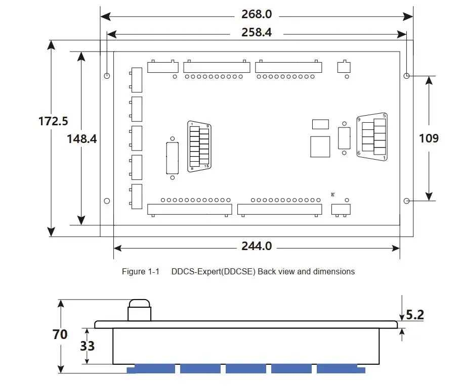
Display size: 7 / 10.2 inches;
Display resolution: 1024 * 600;
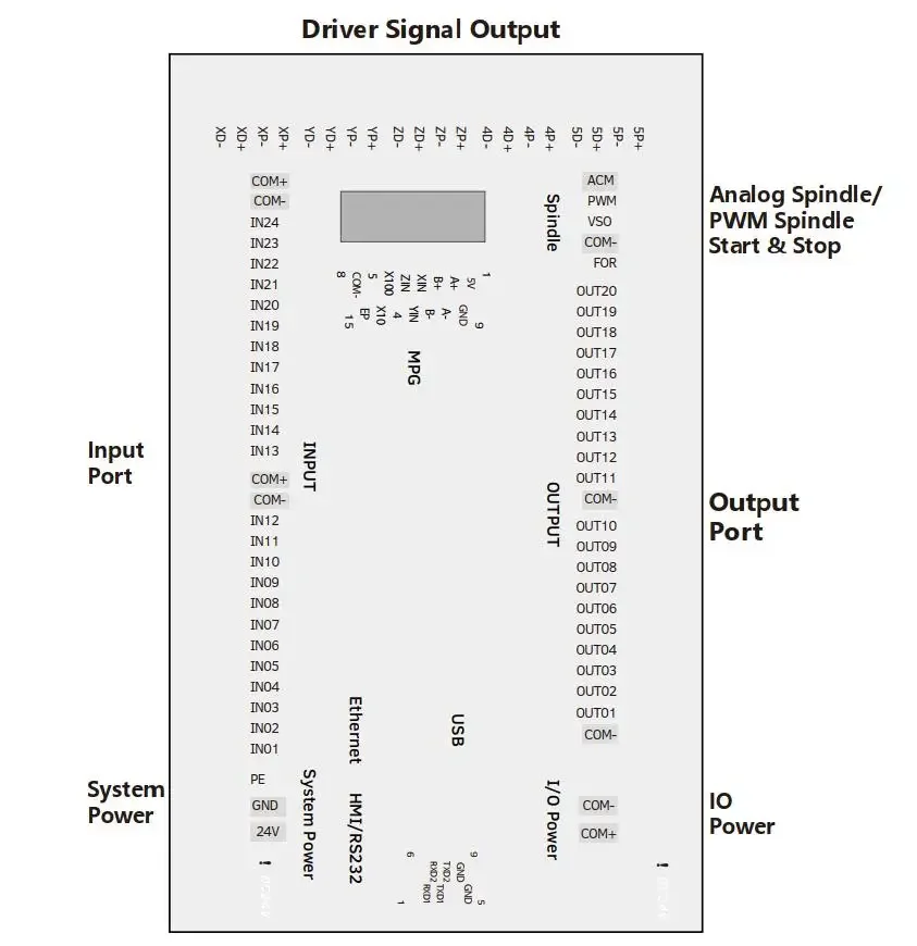
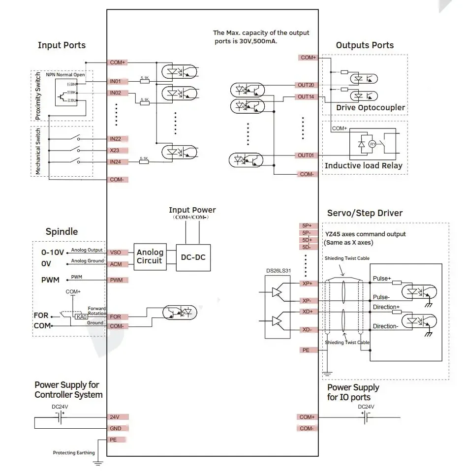
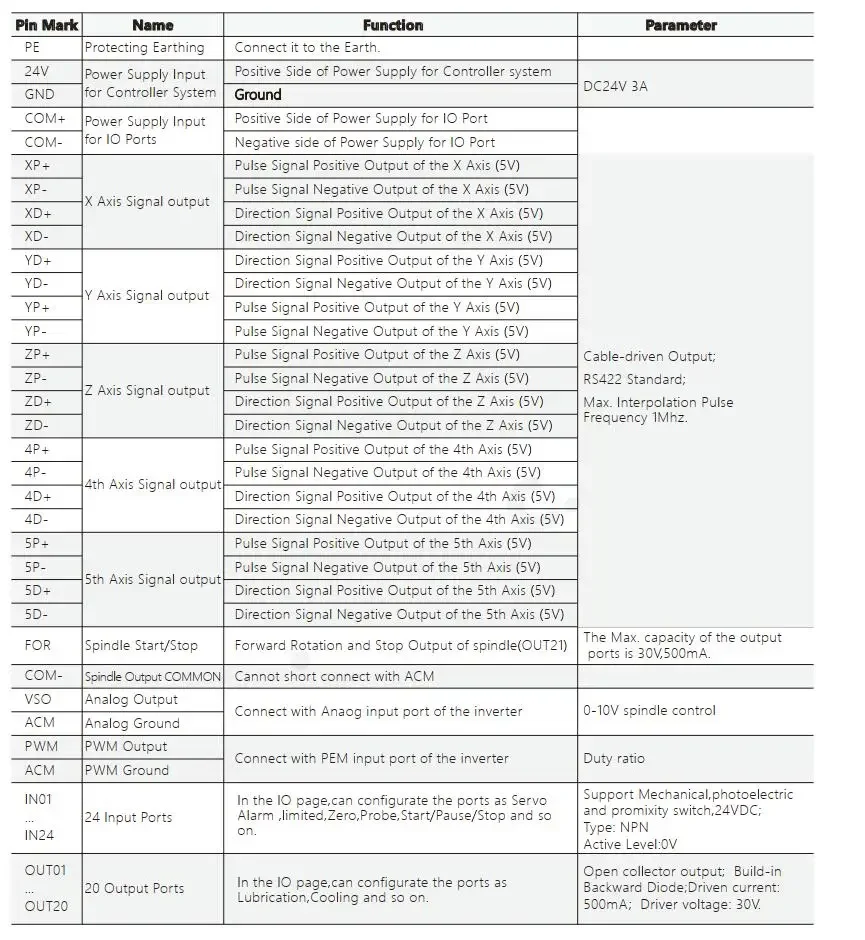
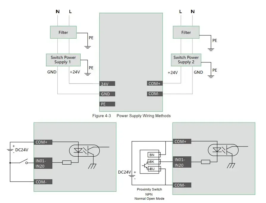
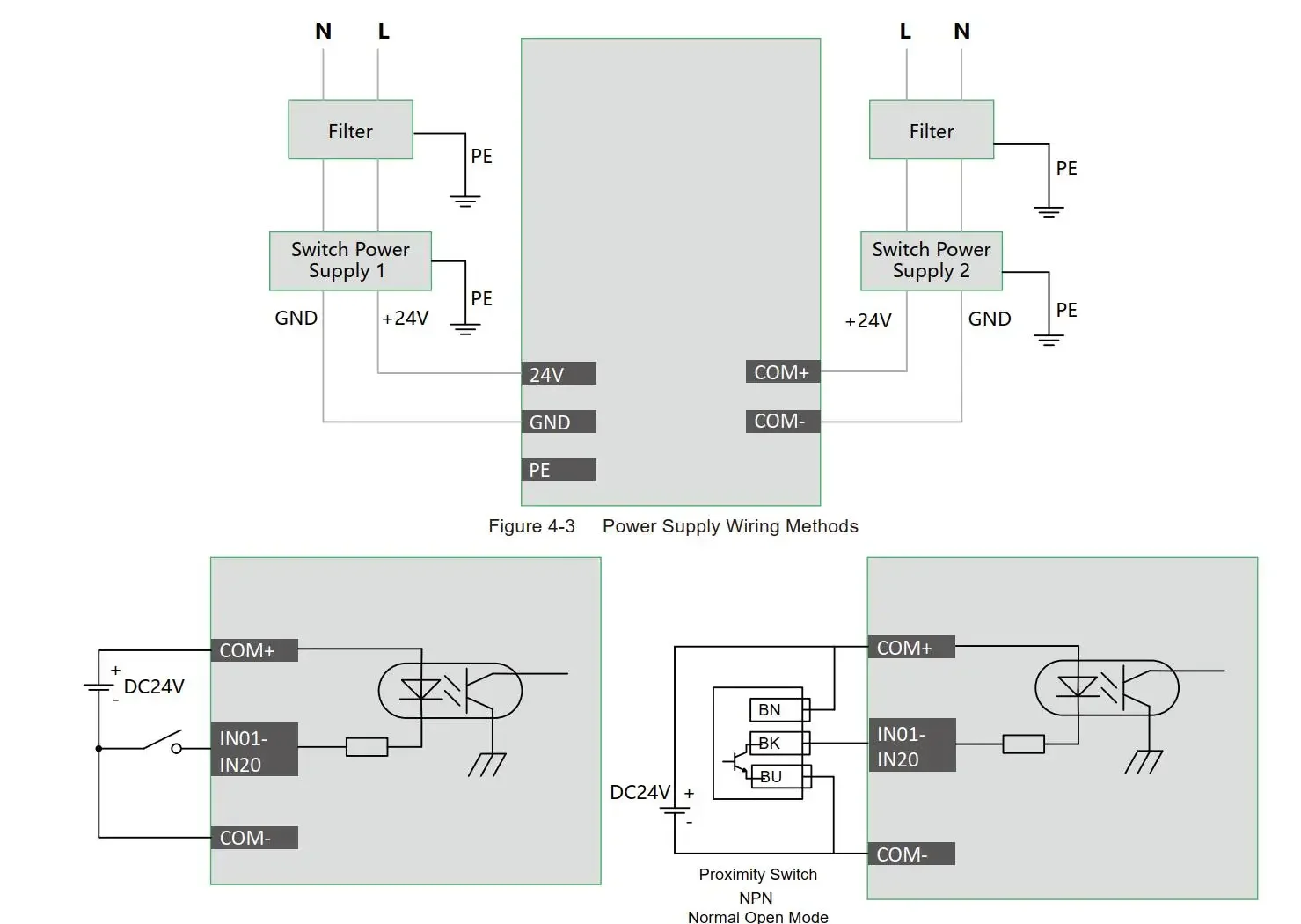
I / O: M6xx standard IO 20/21, M3xx standard IO 24/21;
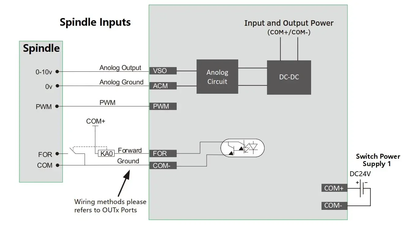
Analog voltage output: 0-10V;
PWM output: only M3xxz support
Tool magazine type: multi-process, straight row, disc;
Tool setting mode: support automatic and manual tool setting;
Tool setting type: fixed tool setting, floating tool setting, first tool setting / second tool setting;
Compensation methods: direction gap compensation, radius compensation, length compensation;
Interpolation algorithm: S-shaped, circular arc hard algorithm, circular arc soft algorithm;
Language: support Chinese and English;
CNC software alarm: program error, operation error, overtravel error, servo drive alarm, etc .;
Network: support file sharing and remote file online processing;
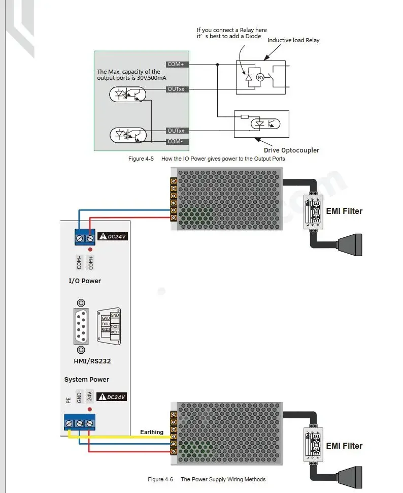
Open collector output, maximum output current 500mA, can directly drive the relay;
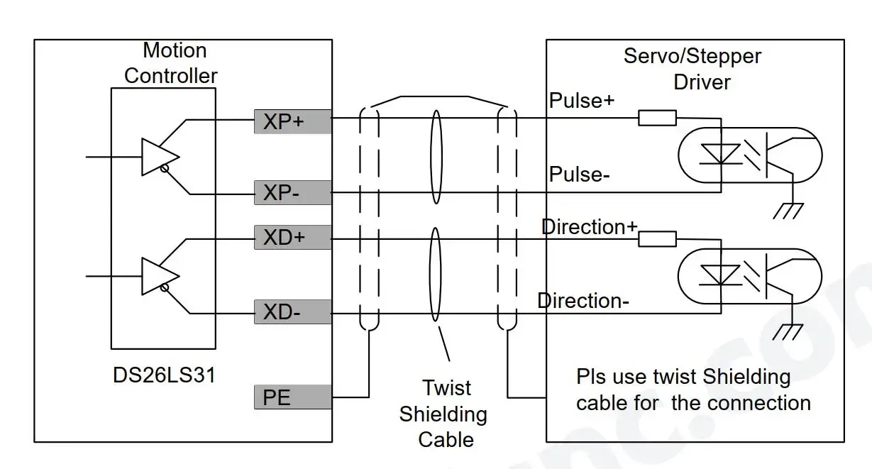
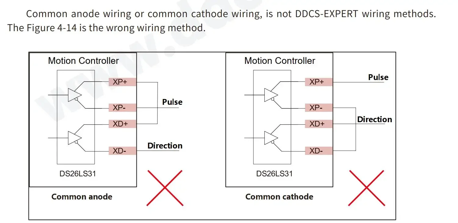
The pulse direction adopts differential output, and the maximum interpolation pulse output frequency is 1MHZ;
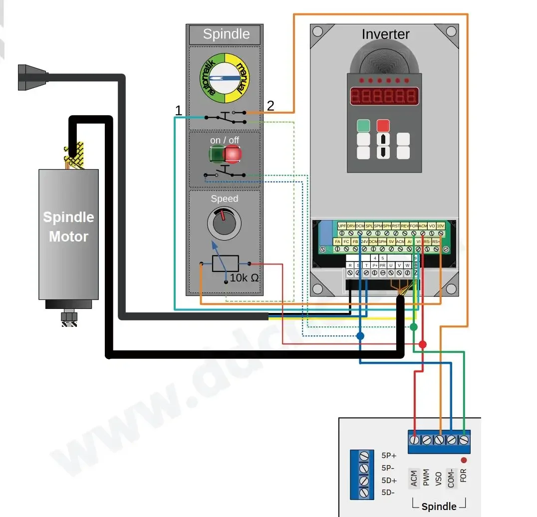
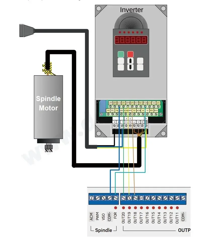
Spindle control mode: multi-step speed (4 steps and 16 speeds), analog (0-10v), servo spindle;
Compatible with standard G codes. Support mainstream CAD / CAM software, such as ArtCam, MasterCam, ProE, etc.
The user interacts with the external file through the U disk and works completely offline;
Multi-stage pretreatment, adaptive speed forward control of processing trajectory, fast processing speed, high precision, and good processing continuity;
Continuous high-speed processing of small line segments, automatically selecting the most efficient algorithm among a variety of small line segment control algorithms;
Support large-capacity file processing;
With breakpoint memory, power-off automatic protection function, near-point processing function, and designated line processing;
Support time lock function;
Support four operation permissions (guest, operator, administrator, super administrator);
With automatic return to origin, return to reference point, workpiece origin saving and loading function;
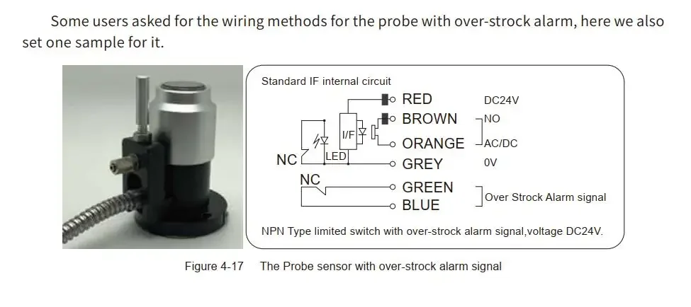
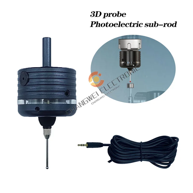
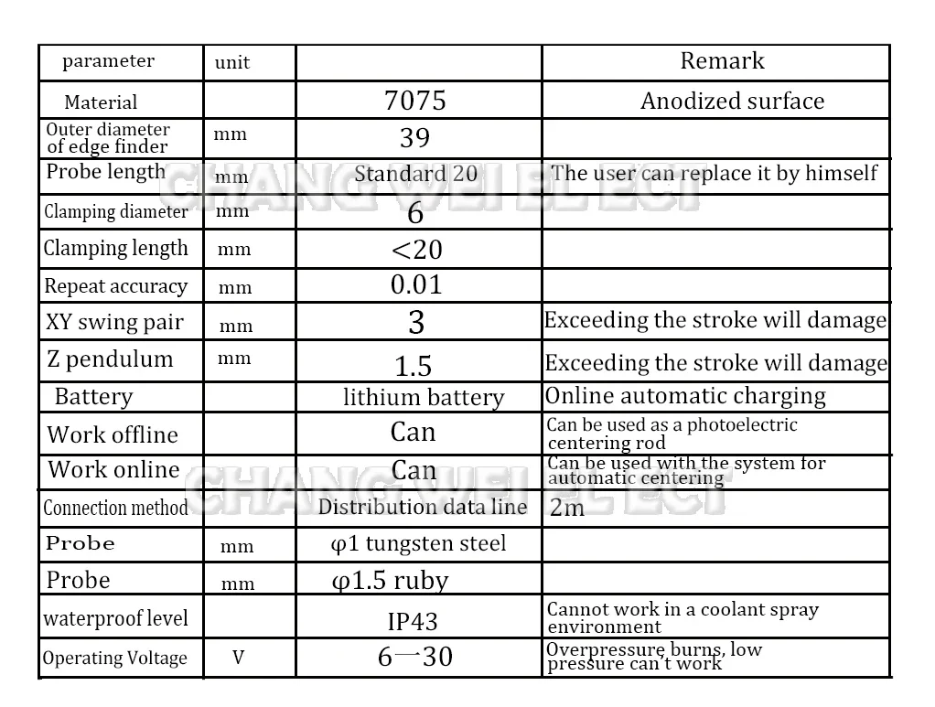
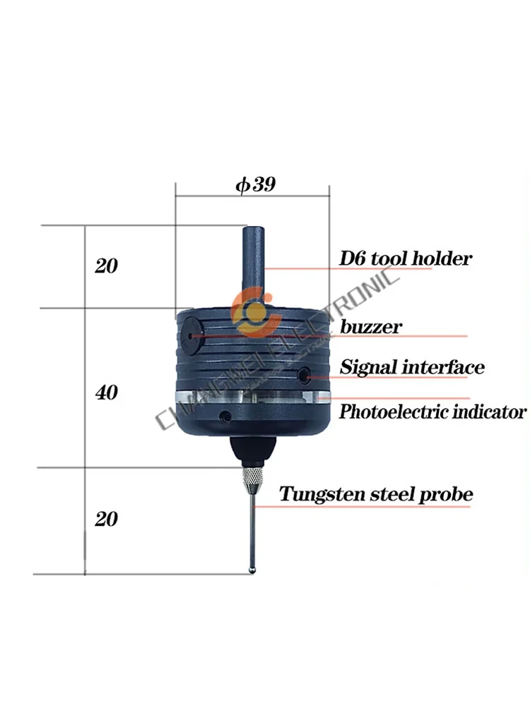
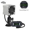
Three-dimensional edge finder 3d probe probe:
The connection can realize online automatic measurement, and the offline can be used as a 5-direction acousto-optic splitter. One machine is multi-purpose, flexible and convenient, with high precision.
1. The repeatability is 0.01.
2. It can measure insulated workpieces.
2. The probe signal NPN does not include the system wiring. You have to read the system manual for wiring. Generally support the tool setting instrument.
Without wiring, it can be used as a photoelectric splitter.
3. Sendstandard macroprogram.
The difference between PCB plastic bracket version and all-metal reinforced version
1. The appearance is basically the same. From the indicator window, the sandwich structure is the metal bracket version, and the pure white bracket is the pcb plastic bracket version. The difference in structure makes the repeat accuracy and stability of the two versions different.
2. The pcb plastic bracket version has relatively low cost, and the structural stability is not as good as the all-metal bracket board.
3. The all-metal bracket version, which fully refers to Renishaw's principle, has a relatively complex internal structure, high cost, repeatability and better structural stability.
The difference between tungsten steel styli and ruby ??styli
The price of the two styli is the same, and the interface is M2.5. The roundness of tungsten steel is better than ruby. Durability is also better than tungsten steel.
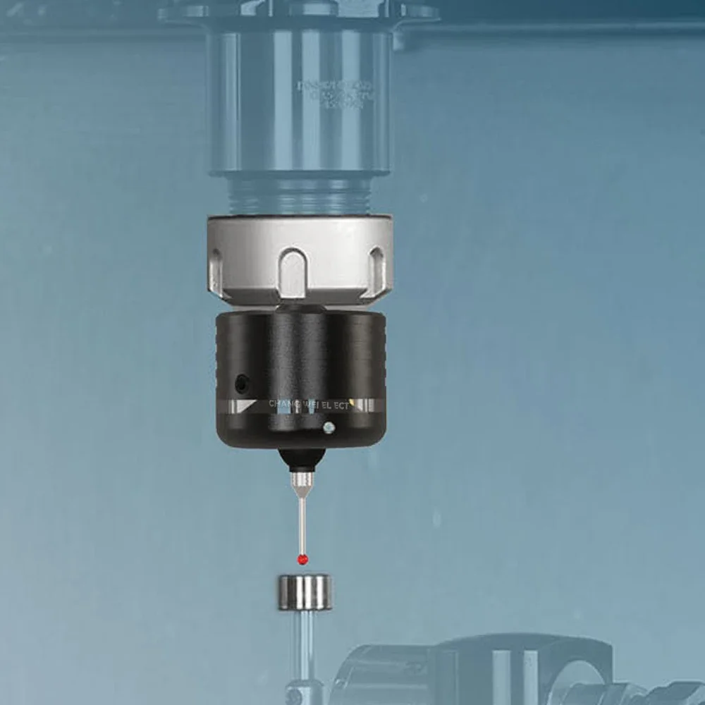
The working principle of the probe
Probe trigger
Gnd and output signal line are connected
After the host computer obtains the signal, it realizes the functions of automatic centering and recording coordinates through the macro program.
There are many types of systems on the market, and you have to complete the wiring macro program yourself.
If you have the system supporting wiring and programming instructions, welcome to discuss wiring methods, system settings, and macro programming.
After purchasing the probe, mach3 and grbl open source script programs can be provided.
For CNC machine users, we can provide Renishaw standard macro programs.
Common problems and improvement methods
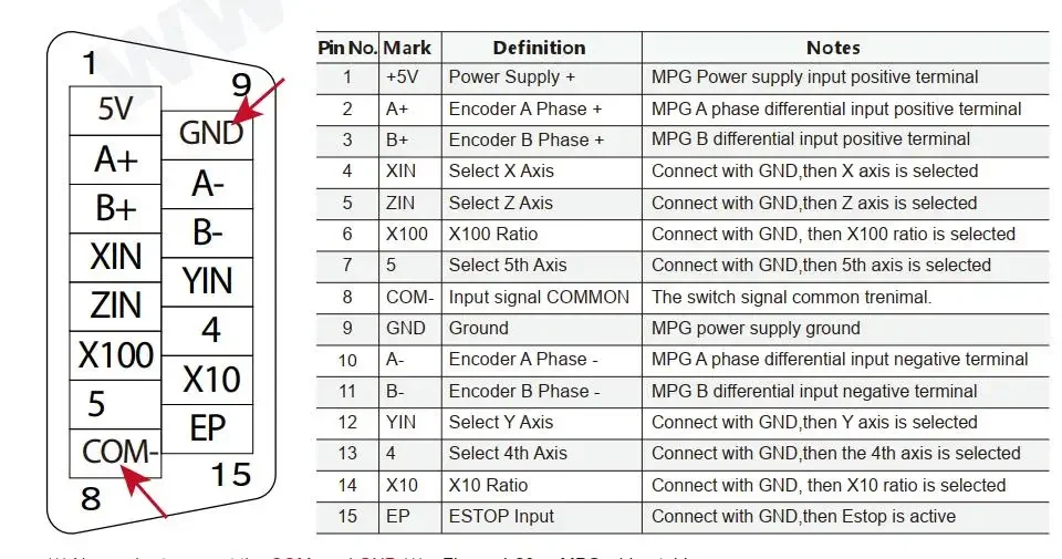
1. Data line connection definition
The red wire is 10 (signal), the white wire is GND, and the yellow wire is 0V (GND).
2. Whether to turn on the spindle speed during detection
A. The edge finder is designed to withstand a maximum rotation of 600 rpm. High-speed rotation will damage the edge finder.
B. When the data line is connected for automatic detection, the spindle cannot be opened, and the rotation will break the data line and damage the edge finder.
C. When the data line is not connected, and it is simply used as an acousto-optic centering rod, it is also possible to turn on the main shaft to rotate at a speed of 600 rpm/min.
Probing directly without opening the spindle.
3. How to judge whether the home position of the edge finder is accurate after the trigger signal?
After the edge finder is installed on the chuck, the table is rotated and adjusted to 0, and the probe is pushed by hand. After the probe is automatically returned to its position, rotate the edge finder to see
Whether the table value is a constant value.
4. Why is the concentricity different after the precise edge finder is reinstalled on the main shaft and the central head?
Every time the edge finder is reinstalled, the concentricity of the spindle and the chuck will be affected by the concentricity of the spindle and the chuck.
Concentricity deviation of the probe into the edge finder.
5. How to improve the detection accuracy when the CNC system of machine tool mechanical structure accuracy cannot be further improved.
A. Rotate the center through the spindle at a speed of 600 rpm (this method can only be used for offline and non-connected work, if you need to rotate the edge finder
Automatic center detection, you can purchase a wireless edge finder to achieve)
B. The deviation of the spindle and the chuck can be adjusted to the 0 position mark by making an edge finder on the spindle and the chuck.
The fixed position and direction of the edge instrument relative to the central head and the main shaft is improved. (The most fundamental solution is to improve
(Spindle and chuck accuracy)
C. The signal processing response time of the edge finder is fixed at about 0.0005 0.0001s, but various grades of numerical control systems and configuration
For sets of circuits, the delay consistency is quite different. When the probe is approaching the measured surface, try to reduce the axis movement speed, which can be
In order to reduce the error caused by the delay consistency problem.


Avaliações
Ainda não existem avaliações.